Big Discount Hydraulic Expansion Joint - A-5 ~Threaded Union – Lide
Big Discount Hydraulic Expansion Joint - A-5 ~Threaded Union – Lide Detail:
Details
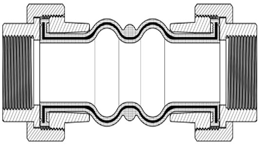
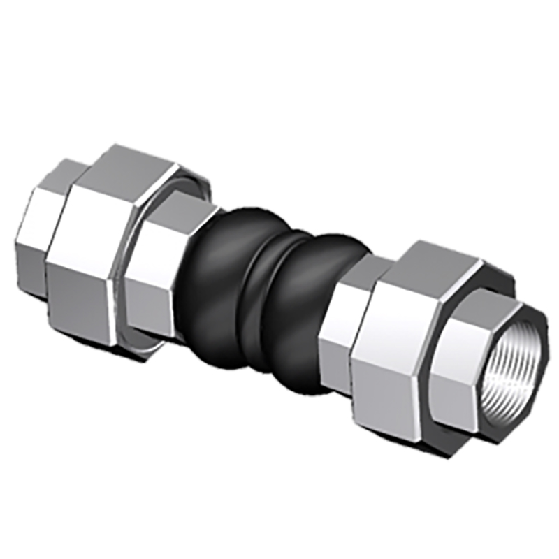
Threaded unions is used When an economical threaded pipe connection is needed, the surface of the union is available both hot-dip galvanizing and electroplating. Both ends provided with a malleable iron union with female thread BS or ANSI.
| Specifications | II | ||
| Working Pressure Mpa (Kgf/Cm2) | 1.6 (16) | ||
| Test Pressure | 2.4Mpa | ||
| Burst Pressure Mpa (Kgf/Cm2) | 4.8 (48) | ||
| Vacuum Kpa (Kgf/Cm2) | 86(660) | ||
| Materials | EPDM/NBR/SBR/NR | ||
| Diameter Range | DN15-DN80 | ||
| Connection Method | THREAD | ||
| Flanges Dimensions | BS, ANSI | ||
| Applicable Medium | Air, compressed air, water, seawater, hot water, oil, acid, alkali etc. | ||
| Loading Port: | Qingdao, China | ||
| Shipment Terms: | FOB, CFR, CIF | ||
| Production Capacity: | 50000 set | ||
| Payment Terms: | L/C, T/T, D/P | ||
| Connection: | THREAD | ||
| Flange Material: | MALLEABLE IRON, DUCTILE IRON | ||
| Period of Delivery | about 21 working days | ||

|
Threaded Union (TU) |
||||||||||||||
|
SIZE |
OAL Length |
Allowable Movement-1 |
Dimensions |
Operating Conditions |
||||||||||
|
Nominal Diameter |
Neutral OAL |
Min Installed |
Max Installed |
Max Compressed |
Max Extended |
Axial Compression |
Axial Extension |
Lateral Deflection |
Angular Deflection |
OAL Fitting |
OAL Body |
Max w.p. (bar) |
Max Vacuum (in. of Hg)-4 |
|
|
Inch |
mm |
|||||||||||||
|
1/2″ |
15 |
8″ |
7.35″ |
8.12″ |
7.13″ |
8.23″ |
0.87″ |
0.23″ |
+/-0.87″ |
±32.2° |
0.92″ |
6.16″ |
150 |
26″ |
|
3/4″ |
20 |
8“ |
7.35″ |
8.12″ |
7.13″ |
8.23″ |
0.87″ |
0.23″ |
+/-0.87″ |
±32.2° |
1.00″ |
6.00″ |
150 |
26″ |
|
1″ |
25 |
8” |
7.35″ |
8.12″ |
7.13″ |
8.23″ |
0.87″ |
0.23″ |
+/-0.87″ |
±25.3° |
1.25″ |
5.50″ |
150 |
26″ |
|
1-1/4″ |
32 |
8“ |
7.35″ |
8.12″ |
7.13″ |
8.23″ |
0.87″ |
0.23″ |
+/-0.87″ |
±20.7° |
1.25″ |
5.50″ |
150 |
26″ |
|
1-1/2″ |
40 |
8″ |
7.35″ |
8.12″ |
7.13″ |
8.23″ |
0.87″ |
0.23″ |
+/-0.87″ |
±17.5° |
1.35″ |
5.30″ |
150 |
26″ |
|
2″ |
50 |
8″ |
7.35″ |
8.12″ |
7.13″ |
8.23″ |
0.87″ |
0.23″ |
+/-0.87″ |
±13.3° |
1.60″ |
4.80″ |
150 |
26″ |
|
2-1/2″ |
65 |
9.6″ |
8.95″ |
9.72″ |
7.13″ |
8.23″ |
0.87″ |
0.23″ |
+/-0.87″ |
±10.7° |
2.00″ |
5.60″ |
150 |
26″ |
|
3″ |
80 |
9.6″ |
8.95″ |
9.72′ |
7.13″ |
8.23″ |
0.87″ |
0.23″ |
+/-0.87″ |
±8.9° |
2.00″ |
5.60″ |
150 |
26″ |
|
Threaded Union (TU)-Jis Standard |
||||||||||||
|
Nominal Dia |
Nominal |
Allowable Movements (mm) |
Installation Tolerances (MM) |
OAL Fitting (MM) |
OAL Body (MM) |
|||||||
|
Inch |
mm |
Length (MM) |
Lateral Deflection |
Axial Extension |
Axial Compression |
Angular Deflection |
Lateral Deflection |
Axial Extension |
Axial Compression |
Angular Deflection |
||
|
1/2 |
15 |
180 |
15 |
10 |
15 |
15° |
6 |
3 |
6 |
7.5° |
30 |
120 |
|
3/4 |
20 |
180 |
15 |
10 |
15 |
15° |
6 |
3 |
6 |
7.5° |
30 |
120 |
|
1 |
25 |
180 |
15 |
10 |
15 |
15° |
6 |
3 |
6 |
7.5° |
30 |
120 |
|
1 1/4 |
32 |
245 |
20 |
10 |
20 |
20° |
8 |
3 |
6 |
7.5° |
35 |
175 |
|
1 1/2 |
40 |
245 |
20 |
10 |
20 |
20° |
8 |
3 |
6 |
7.5° |
35 |
175 |
|
2 |
50 |
255 |
20 |
10 |
20 |
20° |
8 |
3 |
6 |
7.5° |
40 |
175 |
Product detail pictures:



Related Product Guide:
Big Discount Hydraulic Expansion Joint - A-5 ~Threaded Union – Lide , The product will supply to all over the world, such as: , , ,
Products categories
-

Phone
-

E-mail
-

Whatsapp
whatsapp

-

WeChat
Jessy Lin

-

WeChat
Ellen Zhang


