New Delivery for Single Sphere Epdm Rubber Bellow Expansion Joint - A-6 ~Control Units – Lide
New Delivery for Single Sphere Epdm Rubber Bellow Expansion Joint - A-6 ~Control Units – Lide Detail:
Details
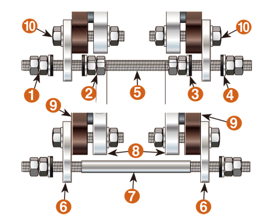
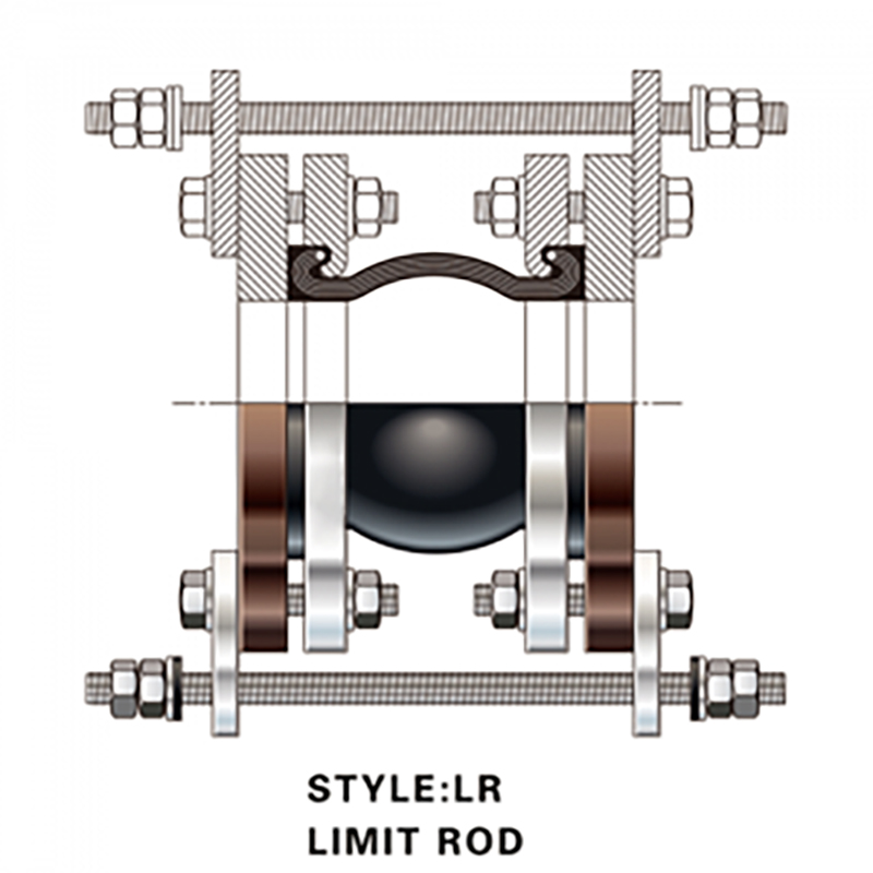
A control unit assembly is a system of two or more control rods placed across an expansion joint from flange to flange to minimize possible damage to the expansion joint caused by excessive motion of the pipeline. The control rod assemblies are set at the maximum allowable expansion and/or contraction of the joint and will absorb the static pressure thrust developed at the expansion joint. When used in this manner, they are an additional safety factor, minimizing possible failure of the expansion joint and possible damage to the equipment. Control units will adequately protect the joints, but the user should be sure that the pipe flange strength is sufficient to withstand total force that will be encountered.
Control units must be used when it is not feasible in a given structure to provide adequate anchors in the proper location. In such cases, the static pressure thrust on the system will cause the expansion joint to extend to the limit set by the control rods which will then preclude the possibility of further motion that would over-elongate the joint. Despite the limiting action that control rods have on the joint, they must be used when proper anchoring cannot be provided. It cannot be emphasized too strongly that rubber expansion joints, by virtue of their function, are not designed to take end thrusts and, in all cases where such are likely to occur, proper anchoring is essential. If this fact is ignored, premature failure of the expansion joint is a forgone conclusion.
|
1 |
Outside Nuts |
|
2 |
Inside Nuts |
|
3 |
Rubber Washer |
|
4 |
Metal Washer |
|
5 |
Control Rod |
|
6 |
Control Plate |
|
7 |
Compression Sleeve |
|
8 |
E.J.Flange |
|
9 |
Mating Flange |
|
10 |
Flange Bolt and Nut |
|
Control Units |
||||||||
|
Nominal Pipe Size |
Maximum Control Rod Plate O.D. |
Maximum Red Diameter |
Maximum Control Plate Thickness |
maximum Tester Surge Pressure Of the System (test pressure is 1.5 times of the working pressure) |
||||
|
Number Of Control Rods Recommended |
||||||||
|
Inches |
2 |
3 |
4 |
6 |
8 |
|||
|
1 |
8.375 |
1/2 |
7/16 |
949 |
||||
|
11/4 |
9.75 |
1/2 |
7/16 |
830 |
||||
|
11/2 |
9.875 |
1/2 |
7/16 |
510 |
||||
|
2 |
11.25 |
5/8 |
7/16 |
661 |
||||
|
21/2 |
12.25 |
5/8 |
7/16 |
529 |
||||
|
3 |
13.25 |
5/8 |
7/16 |
441 |
||||
|
31/2 |
12.625 |
5/8 |
7/16 |
365 |
547 |
729 |
||
|
4 |
13.5 |
5/5 |
7/16 |
311 |
467 |
622 |
||
|
5 |
14.5 |
5/5 |
7/16 |
235 |
353 |
470 |
||
|
6 |
15.5 |
5/8 |
7/16 |
186 |
278 |
371 |
||
|
8 |
19.125 |
3/4 |
7/16 |
163 |
244 |
326 |
||
|
10 |
21.625 |
7/8 |
3/4 |
163 |
244 |
325 |
488 |
|
|
12 |
24.625 |
1 |
3/4 |
160 |
240 |
320 |
481 |
|
|
14 |
26.625 |
1 |
3/4 |
112 |
167 |
223 |
335 |
|
|
16 |
30.125 |
1-1/8 |
3/4 |
113 |
170 |
227 |
340 |
453 |
|
18 |
31.625 |
1-1/8 |
3/4 |
94 |
141 |
187 |
181 |
375 |
|
20 |
34.125 |
1-1/8 |
3/4 |
79 |
118 |
158 |
236 |
315 |
|
22 |
36.125 |
1-1/4 |
1 |
85 |
128 |
171 |
256 |
342 |
|
24 |
38.625 |
1-1/4 |
1 |
74 |
110 |
147 |
221 |
294 |
|
26 |
40.825 |
1-1/4 |
1 |
62 |
93 |
124 |
186 |
248 |
|
28 |
44.125 |
1-3/8 |
1.25 |
65 |
98 |
130 |
195 |
261 |
|
30 |
46.375 |
1-1/2 |
1.25 |
70 |
105 |
141 |
211 |
281 |
|
32 |
49.375 |
1-1/2 |
1.25 |
63 |
94 |
125 |
188 |
251 |
|
34 |
51.375 |
1-5/8 |
1.5 |
72 |
107 |
143 |
215 |
286 |
|
36 |
53.625 |
1-3/4 |
1.5 |
69 |
103 |
138 |
207 |
276 |
|
Maximum Pressure For Unanchored Control Units |
||
|
Test -Design-Surge-Operating |
||
|
Nominal pipe Size |
Style |
|
|
SA,ST,STF,SA,WAF |
DA |
|
|
1-4″ |
175 |
130 |
|
5-10″ |
130 |
130 |
|
12-14″ |
85 |
85 |
|
16-24″ |
40 |
40 |
|
26-30″ |
30 |
30 |
|
Recommended rod units in sizes: |
|
| 1″-8″ |
2 rods |
| 10″-14″ |
3 rods |
| 16″-24″ |
4 rods |
Product detail pictures:


Related Product Guide:
New Delivery for Single Sphere Epdm Rubber Bellow Expansion Joint - A-6 ~Control Units – Lide , The product will supply to all over the world, such as: , , ,
Products categories
-

Phone
-

E-mail
-

Whatsapp
whatsapp

-

WeChat
Jessy Lin

-

WeChat
Ellen Zhang


